|
|
||||||||||||||||
|

The electronics and electrical of the car is quite extensive. There are a lot of electronics that are involved in most all aspects of the build. This page will try to cover some of the generalities of the electrical systems used in the car. The alternator is the stock 110A VR4 alternator. The battery is mounted in the trunk and is a Optima 'redtop'. It is in a NHRA approved battery box. The feedline to the battery from the alternator is a 4 GA. The battery feed line to the cabin controls and engine area is a 0 GA. There is also a seperate 6 GA feed for the radiator fans and related system. |
|
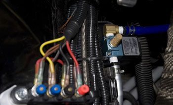
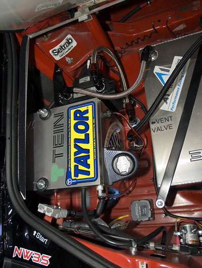
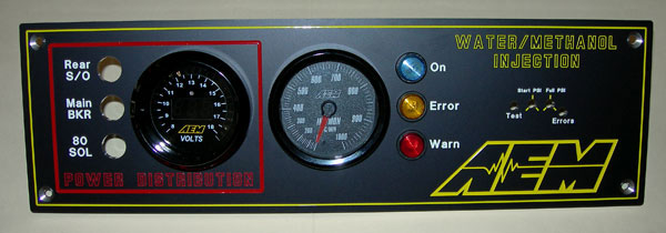
All of the wiring and electronic installations were done in house. We only use soldered and heatshrink terminals. Added special connectors and plated also where required or advantageous to the location or design. Also used extensively are AEM electronics (such as the electronic boost controller shown on the left) |
The main brain of the car is of course the ECU (engine control module). We use the AEM Engine management system. This controls not just the entire engine timing, fuel, cooling, and everything else but does the nitrous system, launch controls (anti-lag and two-step timing retard), turns fans and other things on/off based upon temperatures, and much much more.
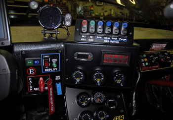
The parameters from this ECU are also put out to the 8" LCD touch screen above the steering wheel and in front of the driver. This means that we can view just about any engine or vehicle parameter at any time. Changing the screen for a different driver or different run, purpose, or track is 1-2-3 and the parameters displayed is adapted. As far as we know, we are the only race car to ever do parameter monitoring and layout this way! |
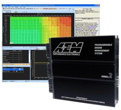 |
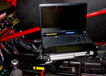
The replacement of the factory ECU is the first step in setting up any car for serious horsepower and racing (or any kind). The flexibility it provides is extremely important as well as all the other parameters needed for complete car control. We have a laptop also plugged into the ECU which further gives us long time logging abilities. We log / record many engine parameters at most all times.
|
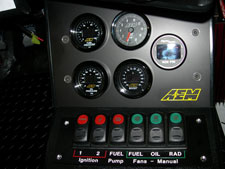
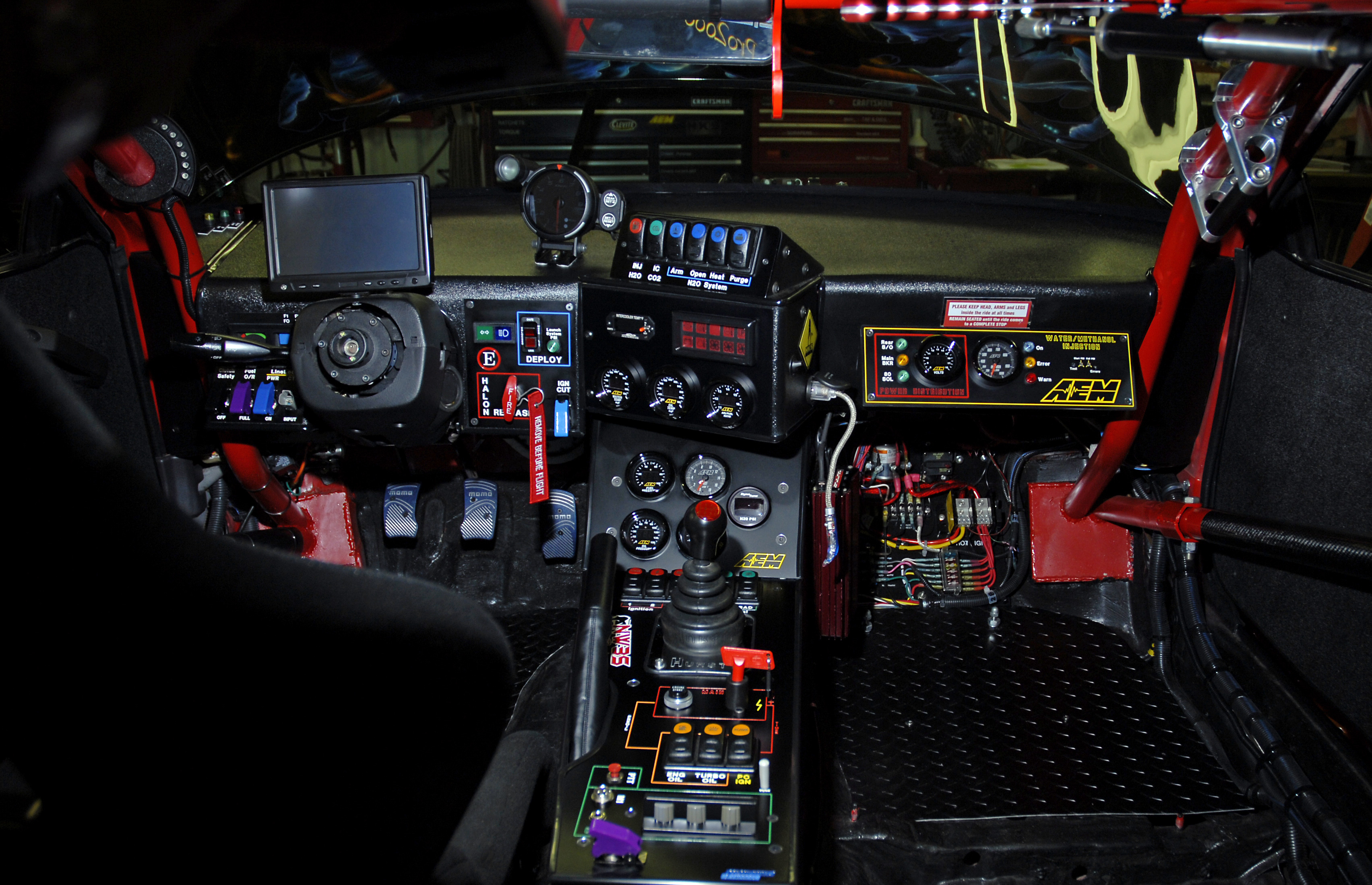
Here's a birds-eye view of the list of controls and indicators inside the car. Here you can also see the LCD screen with the steering wheel removed. The LCD screen obtains it's input graphics from the PC controlled Parameters displayed can be changed to custom screens (for different driver or different
|
|||
|
|
||
|
|
||
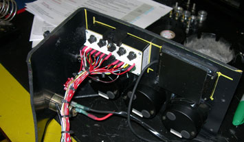 |
Some starting out electrical layouts of warning lights array (left) and one of the power busses for the incab controls. | 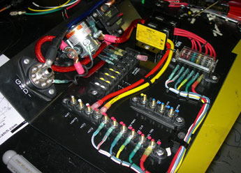 |
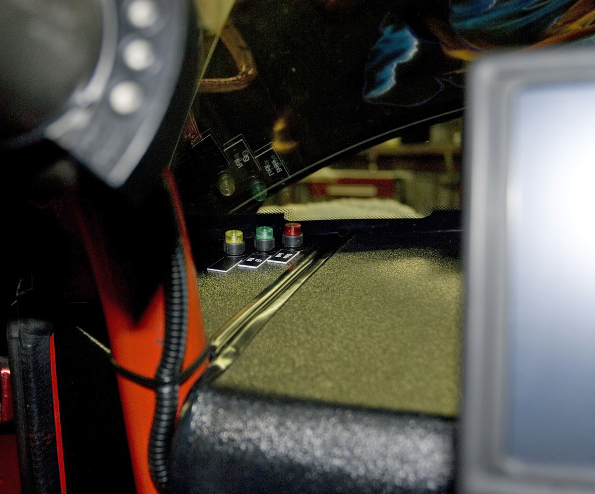
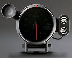
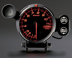
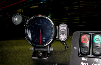
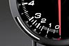
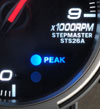
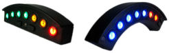
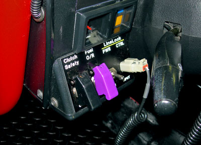
There are many driver indicator and warning systems in the car. On the left you see the Brake Lock and Hydraulic Indicator light. We use HURST brand hydraulic line lock solenoid Just to the left of those in foreground is the progressive Ecliptech shift light system mounted on the A-pillar area of roll bar.. In addition to the progressive shift light we have a DEFI tachometer system (pictured far right) that includes a shift light. While the LCD screen does show the driver the rpms and other parameters we find it is very useful to have a standalone tach and one that is analog. It is fast to read while still being able to judge in advance the rate of increase or decline. It is also there if a parameter screen fails (backup). One of the nicest tachometers I've ever worked with! The only problem with DEFI is they change models so frequently and then drop other previous models it is hard to keep up and / or get parts for their older electronics. That and some of their items I had as favorites they don't make anymore. Seems they change every 2 years or something. PITA.
For the most part the main shift light used is the progressive Ecliptech shift light system. Because the lighting is progressive is makes it much easier and faster to time the shift at the exact moment, |
|
|
Left trunk area showing the battery (in NHRA box), fuel cooler is in front of that. Voltage meter for quick status read and fuel pump/system fuses and solenoid. |
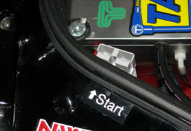
High current connection (200 Amp) for a fast jump to the main battery if needed. Forklift style connector makes it easy and heavy duty.
The control area in the cab (forward passenger side area) monitors the battery voltage and which power controls are one or off (rear main power, cabin power, 80A solenoid control feed).
As with many of the images on this page you can see more detailed photos and angles at the photo interior section of the website. Further specifications about the installed AEM water injection system are at the OTHER section of the build pages. |
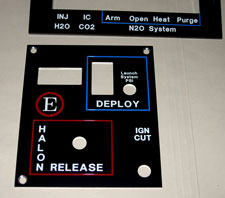
Launch control area Switches for:
Above that is the fuel cell level gauge and warning indicators. |
 |
|
We utilized CNC custom switch plates with color inset and aluminum engraved. Panels made by FrontPanel Express company. For gauges we use mainly the AEM digital series. Digital is much faster reading than analog. We would have gone AEM serial gauges but we need the laptop hooked up at the same time and that can cause a problem. So standalone digital gauges was the answer. Some systems or installs are borrowed from the aircraft industry or custom made for us (such as the cobo switches from Italy). |
All of the controls and switches can be viewed further at the WhatIsIt page. Much of these controls are automated and do not need driver intervention or input. Other uses involve over-ride for safety or redundancy. |
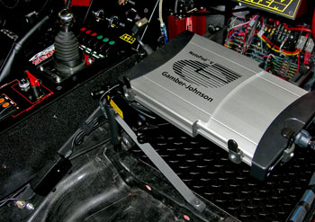 |
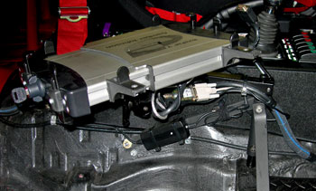
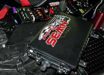
We use a Gamber-Johnson PC (laptop) mount. This is the same style and model used in many emergency vehicles and is super heavy duty. The mount has to be very solid but still be able to rotate and swing where we want it. Either for tuning, or up out of the way, or for enabling the logging functions (one of the more important aspects of the PC in the car). Here is a view of the mount without the PC installed and in two different positions. It can quickly telescope or rotate for access by driver, passenger side, or inbetween then swung out of the way safely. |
 |
 |
 |
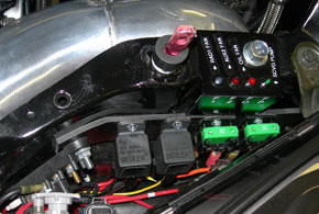 |
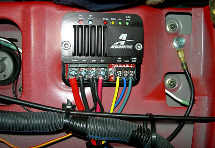
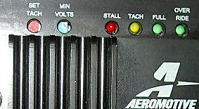
On the left is the under-hood fan power buss and the indicator system (behind driver side headlight). This is for quick monitoring of the cooling fans (radiator and oil cooler) and turbo scavenge pump operation when working on a running engine and at the track. For more on the cooling system and/or fans see the ENGINE area of the build menu.
On the right is the fuel controller in the trunk area. There is not a lot of info on this page on the fuel system or nitrous as those are covered in their own page (see build menu). More on the fuel system can be found HERE |
|
 click for larger view |
Our rocker switches were made for us by a company in Italy. Cobo International made us some awesome custom rockers and they look great. They were pricier than just going plain but unique sometimes is worth the extra effort (or price). They also made our custom warning indicator panel and fuel level system. For each area of the control system, photos, or a more specific labeling of what each does you can go to the WHAT IS IT page and each section can be clicked on for a close up and explanation of each control panel or system. |
 |
 |
|