|
|
||||||||||||||||
|

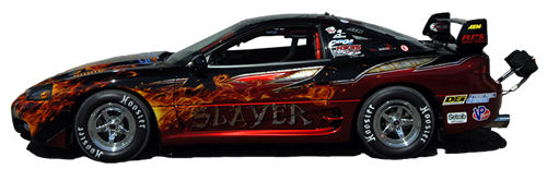
| The fuel system is a critical part of any race car. We worked with Aeromotive company on the design and equipment to make sure we had what we needed for now and the future. The fuel tank was removed and an aluminum racing fuel cell (15 gallon) was installed. Stock fuel lines were also removed and replaced with SS braided -10AN fuel lines. Below are some photos and specifications on the NW3S 3000GT race car's fuel system. System is designed to use high octane race fuel (see fluid section for more info) of which we current use VP Q16. |
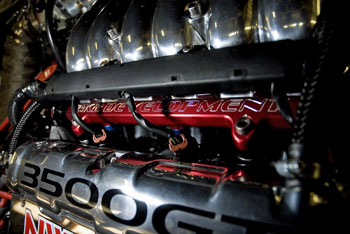 fuel rail and injectors installed in the 3000GT VR4 Racecar |
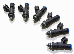
One of the most critical for performance are the fuel injectors. It is also not just size that is important to fuel flow but quality and reliability across the different flow rates and voltages. Because of this we chose Injector Dynamic brand fuel injectors. We currently are running (6) 1000cc injectors but will be increasing this near the beginning of 2013 when a larger Q16 compatible injector is available.
These are saturated high impendence injectors.
|
|
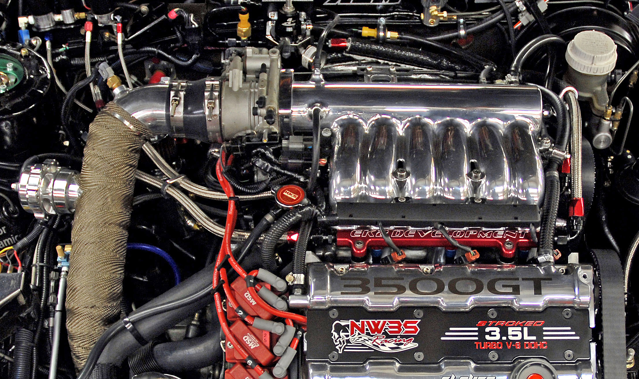
Fuel rails and front injectors view on the |
||

|
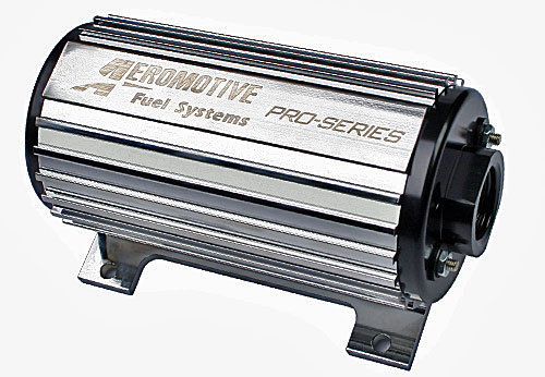
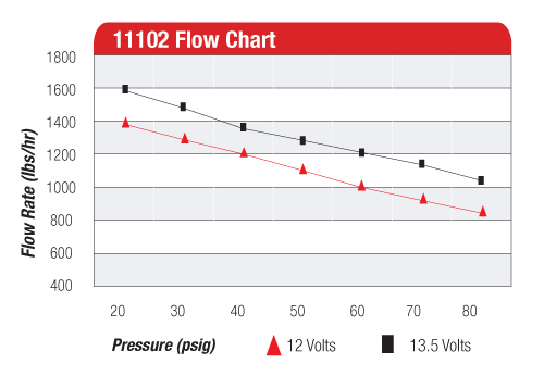
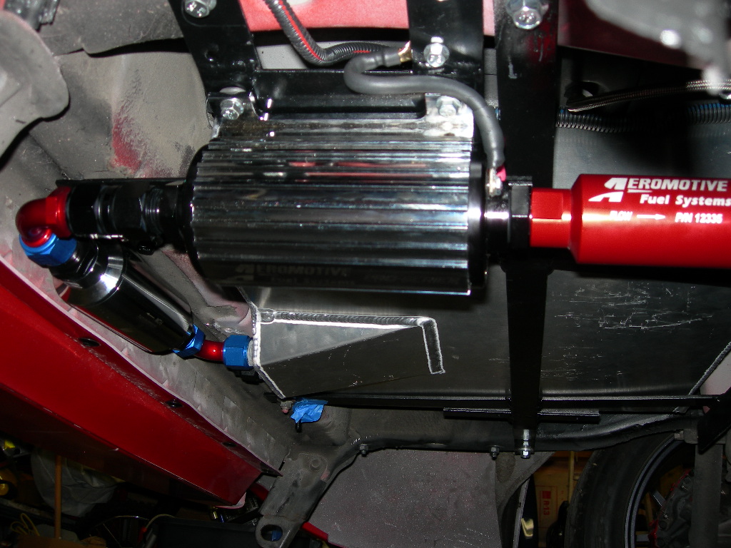
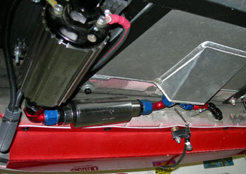
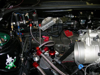
Next up is the fuel pump. We use the Aeromotive 11102 Pro-series fuel pump. It has some serious flow abilities and is second to none. With a flow to support over 2500 horsepower and -12AN inlet/outlet it outperforms other pumps easily. Note that it is fairly loud (compared to stock) and wouldn't be considered for a daily driver. We use some special mounting material to quiet it down some though (much like the material used on submarines for equipment silencing). Choosing one large instead of multiple pumps in series is the best way to go we think. This makes sure that if you have a pump failure it is known immediately (your engine stops!). With multiple pumps you can lose 1 pump and the starve your engine of the fuel it needs. This would basically destroy the engine. Multiple pumps also means more to fail (moving parts) and many times increased electrical load. On the left is the pump load chart showing the flow rate of the pump.
The fuel pump is fed by a -12AN line. This large diameter line comes out of the fuel cell and into a pre-filter then into the pump. All connections and outlets are -12AN size. The outlet of the pump is brought down to -10AN size. The -10AN braided fuel line then goes up to the engine compartment. Prior to the fuel rails there is another fuel filter. The other (drivers side) port out of the fuel cell is the fuel petcock shut off right after the fuel pump. This is important for engine removal or fuel line removal.
The line below the fuel cell in the clamp is the parachute release cable |
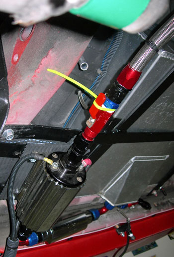
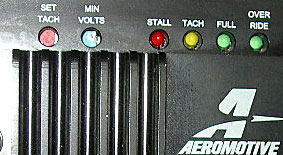
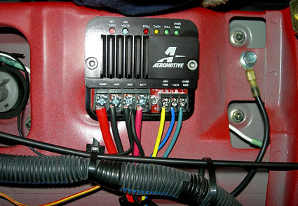
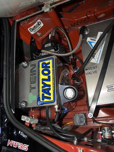
This is the billet fuel controller (aeromotive 16306) which handles the voltage requirements and variations to the fuel pump depending on the call for fuel. Based upon RPM or an over-ride control in the cab this provides reduced flow when just idling and full flow for racing.
|
|
|
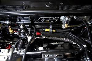
On the left are the lines as they come from the fuel pump to the last filter. Size to here is -10AN. From here the -10AN lines are wyed to (2) -8AN lines to each fuel rail. The nitrous pressure safety solenoid and then fuel feed is also tapped off at this point. In the right is the Fuel Pressure Regulator mounted on the firewall with the feed line, return line, incab gauge pressure sensor and under-hood pressure gauge. We use the aeromotive pro-series regulator model 13110 Lines are SS braided fuel lines and all lines near the firewall are protected by the top-of-the-line DEI iron-oxide/silicone heat wrap. |
|
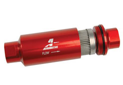 main fuel filter |
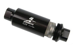 pre-pump filter |
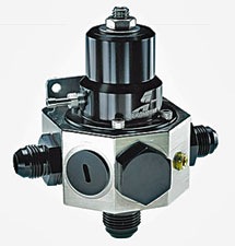 fuel pressure regulator |
 |
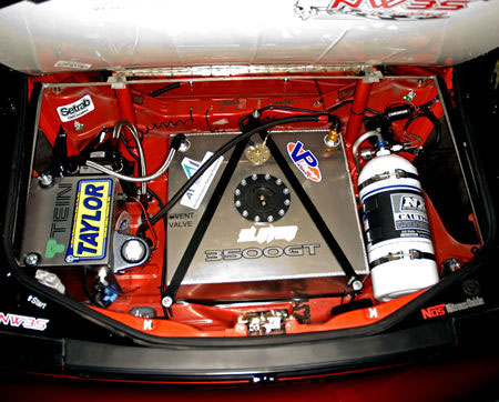
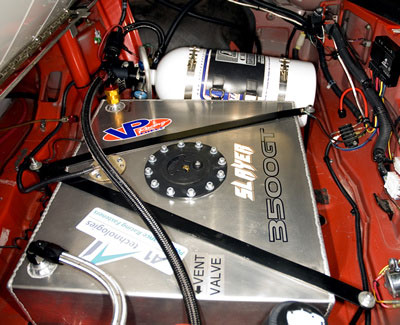
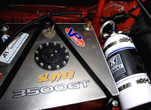
Now for the trunk. On the left you see the firewall and cover for the fuel area of the 3000GT race car. Firewalls are required by NHRA (or mounted outside cabin like stock).The firewalls we use are custom made from sheet steel. On the right you see the overall whole trunk area. With a 15 gallon fuel cell in the center, strapped down and grounded. The nitrous tank is on the right side (for more on nitrous oxide install see that other webpage). Battery box on the left. |
 |
|
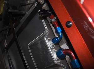
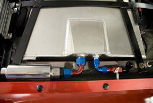
Aluminum fuel cell for racing. 15 gallon capacity, fuel level float installed. Fuel cells also have an open-cell foam in them to prevent explosions. Fill is in the very center (the black round cap). Nitrous oxide tank to the right of the fuel cell. The fuel return line (from the fuel pressure regulator) is on the left side top of tank and is a -6AN SS braided line. The vent line is on the right and includes the rollover valve which prevents fuel leakage out the vent line in case of a vehicle rollover (NHRA safety requirement).
|
 |
Bottom view of fuel cell. The out line to the fuel pump (first to the pre-filter) is -12AN. The other side is the drain line for draining the tank for fuel change or storage/winter. |
 |
This view shows the fuel cooler (in front of the battery box). The return line from the pressure regulator (in engine compartment) is a -6AN SS braided line. It connects to the bulkhead connector in the floor, goes into the Setrab fuel cooler, then out to the fuel cell. The fuel cooler has an assist fan that can be enabled in the cab by the driver as needed. This helps keep the race gas cooled down rather than superheated by the outside ambient temperature or the constant flow through the pump and back. Also shown is the shutoff petcock for the vent line at the floor level (the black fuel line).
More photos of the fuel cell area can be viewed at the trunk photo section.
|
 |
 |
 |
|